


 Rebuilding Coleman® Single Burner Stoves
Chapter Three: Reassembly
![]() My video on how to reassemble a single burner stove can be found here.
My video on how to reassemble a single burner stove can be found here.
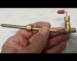
3.1 Reassemble the valve. Gather your valve body, valve stem, valve stem nut and the packing retainer. If you removed the old packing during the cleaning process, have the new one out too.
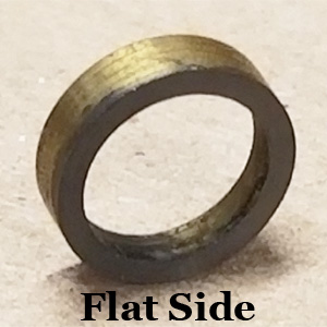
Start by sliding the packing retainer over the end of the valve stem. Notice that one side of the retainer is flat (Figure 1) while the other is beveled (Figure 2).
![]() Warning: The beveled side of the packing retainer must face the retainer stop on the valve stem.
Warning: The beveled side of the packing retainer must face the retainer stop on the valve stem.
 |
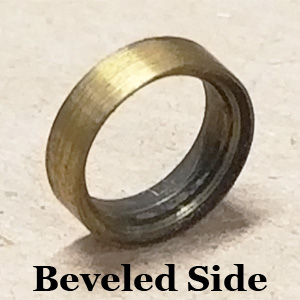 |
Figure 1 |
Figure 2 |
Slide the retainer on beveled side first so that it fits over the retainer stop ("C" clip). Follow this with the new valve stem packing (if replaced) and then the valve stem nut (Figure 3).
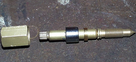 |
Figure 3 |
Insert the conical end of the valve stem into the valve body and turn it clockwise until it stops.
Slide the valve stem nut forward while turning it clockwise. Once you have the threads started, continue turning with your fingers until it becomes tight.
Gather your fuel & air tube, the metering rod and the spring. Slide the spring over the metering rod and then insert the rod into the fuel & air tube. Press down on the top of the metering rod down to ensure it can travel freely. Insert the fuel & air tube into the bottom of the valve. Turn it clockwise and snug with a 5/16” end wrench.
Place the valve body in your bench vise. Tighten the valve stem nut 1/2 turn and stop. Turn the valve stem counterclockwise and the back clockwise and take note of how much resistance the stem offers you. If it is very easy to turn with little or no drag, your valve stem nut is not yet tight. Turn the valve stem nut another 1/2 and try again. Continue this process until you feel a good bit of drag turning the wheel.
 Note: This is the safety check of the stove's retainer stop. It is critical that it passes this test.
3.2 Test the valve stem retainer stop. Turn the valve wheel fully counterclockwise until it stops. Once you have reached this point, briefly try to turn it counterclockwise even farther. If it turns, your retainer stop has opened around the valve stem and needs to be repaired. This would most likely happen with a 500 series stove or 242 series lantern that had valve stem disassembled but I recommend you do this test regardless of what stove or lantern you are rebuilding.
If it is “locked” and will not turn any further, the retainer stop is working properly. Return the stem to the fully clockwise (closed) position.
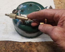
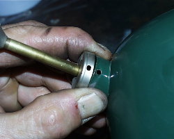
3.3 Install the valve. Insert the fuel & air tube into the hole in your fount and turn the valve clockwise to install it (Figure 4). Turn until it snugs up, then continue turning it with just your hands as far as you can without assistance from a tool.
![]() Thread lock is not required when installing the valve. I have been rebuilding lanterns and stoves for 20 years and have never needed it. Coleman sometimes used Loctite Red #262 or Gasoila Hard-set. You can use these, or Loctite Red #545 if you choose to, but never use pipe-dope or Teflon tape.
Thread lock is not required when installing the valve. I have been rebuilding lanterns and stoves for 20 years and have never needed it. Coleman sometimes used Loctite Red #262 or Gasoila Hard-set. You can use these, or Loctite Red #545 if you choose to, but never use pipe-dope or Teflon tape.
The 502 valve is located on the side of the fount, and the valve wheel will face towards the fuel filler hole. To find the exact position the valve needs to be in, set the burner support down on the fount and align the three holes. When properly positioned, the fuel inlet tube will rest in the "U" of the burner support as shown in Figure 5.
Place the fount upside-down in your bench vise, just as you did when removing the valve. Use firm and even pressure as you slowly rotate the fount. Once you feel the valve starting to get tight, continue to turn it until the valve stem reaches the proper position.
 |
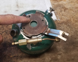 |
Figure 4 |
Figure 5 |
Please refer to the pictures you took of your stove when determining the proper position of the valve.
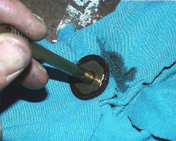
3.4 Install the check valve. If you left the check valve in your stove earlier, you can bypass this step. Take your new (or cleaned) check valve and remove the air stem. Tilt the fount on its side and drop the check valve down into the cylinder. Use a flathead screwdriver to turn it clockwise until snug.
3.5 Install the air stem. Lower the bottom end of the air stem into the pump plunger hole, then turn it clockwise to install in the check valve. Finger-tight is fine.
3.6 Install the pump. Gather your pump assembly to include the pump clip or screws. Ensure that all of the excess oil has been removed from in and on the pump (Figure 6).
Direct the bottom of the pump down into the cylinder, guiding the air stem into the hollow pump shaft (Figure 7). At the same time, start tucking the edges of the pump cup inside the cylinder. Ensure that the cup does not roll or catch an edge as you slide it down in the cylinder.
 |
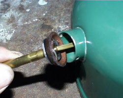 |
Figure 6 |
Figure 7 |
Press the pump down in the cylinder. Carefully fit the pump cap over the edge of the pump cylinder, ensuring that the “oil” hole is above the shaft and that the screw/clip holes in the pump cap are aligned with those in the fount (Figure 8). Press down evenly and firmly to align the holes.
With the pump cap properly aligned, install the pump clip or screws to secure it. If you have a pump clip, insert one end in one hole, then use needle nose pliers to guide the other end into the second hole (Figure 9). It can be a tight fit so use caution so you don't scratch anything.
Press the pump all the way to the bottom and rotate it clockwise until it stops.
 |
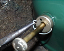 |
Figure 8 |
Figure 9 |
3.7 Install the fuel filler cap. Set your filler cap insert on the fount and then loosely install the filler cap over it. Before the cap gets tight, install the insert screw. Once you have it started, fully tighten down the filler cap and then take a screwdriver and tighten the insert screw. You will notice a space between the screw and the cap--this is normal.
3.8 Pressure test the fount. Fill the fount at least half-way with fuel, then install the filler cap and tighten it. Before starting, wipe off any fuel that may have spilled on the fount. Set it on a dry paper towel for testing. Keep your ears and eyes open for leaks.
![]() Note: These tests assume that your fuel filler cap/gasket is new, or in very good working condition.
Note: These tests assume that your fuel filler cap/gasket is new, or in very good working condition.
Place the valve wheel on the end of the valve stem and make sure the valve is fully clockwise. Rotate the pump handle one turn counterclockwise, grab the pump with your fingers and plug the hole with your thumb. Over-pressurize the lantern by giving it 50+ pumps then rotate clockwise to close the pump.
Listen for air escaping and watch for wet spots. Areas to look closely at:
Valve-to-fount junction. Watch for the slightest amount of dampness or bubbles from around the threads. If you note a leak you probably need to turn the valve in the fount one more turn.
Valve stem nut. Look and feel for dampness along the bottom of the valve stem and nut. A leak here indicates that the stem packing has not been sufficiently tightened.
Bottom of the fount. If you see ANY dampness on the bottom of the fount or on the paper towel, you need to find the source of the leak.
Warning: ANY hole or crack in the fount renders the stove unsafe to use. Don't take the chance by trying to fix it with body putty or POR-15®. Get a replacement fount or set it on a shelf for display. DO NOT USE THE FOUNT.
3.9 Test the check valve. Turn the pump handle counterclockwise two full turns to open the check valve. Lightly rest your finger over the hole on the pump. Do not press down. What does the pump do?
If it does nothing, your check valve is working properly.
If it raises up, it is leaking. How fast it comes up tells you how bad the leak is. If it rises bottom to top in under 5 seconds, it is leaking too much to be safe.
Remove the pump and shoot some carburetor cleaner at the check valve to see if you can clean it better. If you cannot stop the leak, I recommend you remove the check valve.
If the pump rises slower than previously mentioned, you might be okay because the air stem is a positive stop (supplement) for the check valve.
You are the only one who can decide if your check valve is working well enough to be safe. The 5 second rule is only a guideline.
3.10 Install the collar, Bunsen and burner support. Using caution not to scratch the Fount’s paint. Slide the burner support arm into the collar's slot from the top. Insert the Bunsen into the center hole of the burner support then set the collar down on the fount and hold it. The “arm” of the burner support should align with the valve's fuel inlet.
With the burner support properly positioned, install the three screws to secure it (Figure 10). Ensure the collar is flush against the fount.
3.11 Install the burner bowls. Sit your outer burner bowl down on the collar. The smaller of the two side holes will sit directly over the burner support’s arm (Figure 11).
 |
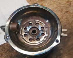 |
Figure 10 |
Figure 11 |
Thread the inner burner bowl on to the Bunsen as shown in Figure 12. Spin the bowl until it gets tight.
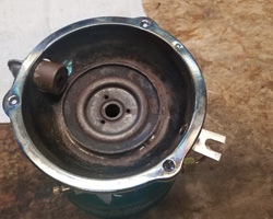 |
Figure 12 |
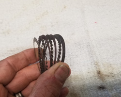
3.12 Install the burner cap and filler rings. Gather the filler rings, three screws and the burner cap and set them down in front of you. Alternate your filler rings flat then corrugated and make the top and bottom one flat (Figure 13). Set them down centered on the inner burner bowl.
Place the burner cap on top of the filler rings in a manner where the screw holes will line-up with the screw holes in the inner burner bowl. Loosely install all three screws. With your fingers, center the filler rings under the burner cap (Figure 14) and then tighten the three screws.
 |
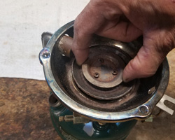 |
Figure 13 |
Figure 14 |
3.13 Assemble and install the regulator assembly. Turn the regulator lever so that it is facing the end where the generator will mount. Unwrap your new generator and set it on your workbench, being careful to keep the internal parts tucked-up inside. Slide the jamb nut over the end of the generator and then insert the crooked end of the generator tip cleaner into the hole in the eccentric block (Figure 15). Gently slide the generator tube down on the regulator and the slide the jamb nut down and thread it on with your fingers. Hold the regulator in your bench vise and tighten the jamb nut with a 7/16" end wrench.
Insert the end of the generator into the hole in the side of the outer burner bowl and push it towards the Bunsen. Once it reaches the Bunsen, insert the tip into it. This will also bring the regulator assembly to the slot on the burner support arm. (Figure 16). Tighten the lock nut with your 1/2” end wrench.
 |
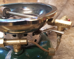 |
Figure 15 |
Figure 16 |
Press the fuel inlet tube up into the bottom of the regulator, then thread the nut to the bottom of the regulator assembly (Figure 17). Tighten it with your 7/16” wrench.
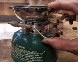 |
Figure 17 |
3.14 Install the grate. Set the grate on the outer burner bowl and use the three screws to secure it. Tighten with your cross-tip screwdriver.
3.15 Install the valve wheel and direction disk.
Place your valve wheel over the end of the valve stem and ensure the stem is fully clockwise. Set your direction disc inside the recessed area of the wheel and then thread the screw into the end of the valve stem. Ensure the direction disk is property positioned and tighten the screw.
3.16 Prepare for lighting. Ensure your Filler Cap is tightened down.
![]() Caution: Ensure you have a fire extinguisher close-by before proceeding!
Caution: Ensure you have a fire extinguisher close-by before proceeding!
Twist the pump handle counterclockwise and pump the Fount 20 times. Turn the pump handle clockwise to close. Turn your valve wheel counter-clockwise one-quarter turn, then watch and listen. You should hear a gurgling sound inside the fount, followed shortly by a spitting noise. When you hear the spitting sound, turn the Valve Wheel fully clockwise to close the Shut-off Valve.
Check one more time for leaks. If you see a leak, tighten the junction to stop it.
3.17 Light the stove. Ensure that the regulator lever is facing outboard, or away from the stove. Hold a lit match or lighter over the burner and turn the valve wheel counter-clockwise one-quarter turn until it ignites. As the generator continues to get hot, the flames will go down and start to turn blue. Allow the stove to burn for a minute or so like this, then open the valve. Pump more air into the stove if necessary. You can control the amount of flame with the regulator lever.
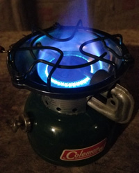 |
Congratulations! You're done!