


 Rebuilding Coleman® Single Mantle Lanterns
Chapter Three: Reassembly
![]() My video on how to reassemble a single mantle lantern can be found here.
My video on how to reassemble a single mantle lantern can be found here.
3.1(a) Reassemble the valve (200 series). Gather your valve body, valve stem, valve stem nut and the packing retainer. If you removed the old packing during the cleaning process, have the new one out too.
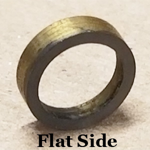
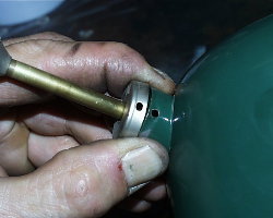
Start by sliding the packing retainer over the end of the valve stem. Notice that one side of the retainer is flat (Figure 1) while the other is beveled (Figure 2).
![]() Warning: The beveled side of the packing retainer must face the retainer stop on the valve stem.
Warning: The beveled side of the packing retainer must face the retainer stop on the valve stem.
 |
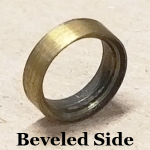 |
Figure 1 |
Figure 2 |
Slide the retainer on beveled side first so that it fits over the retainer stop ("C" clip). Follow this with the new valve stem packing (if replaced) and then the valve stem nut (Figure 3).
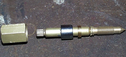 |
Figure 3 |
Insert the conical end of the valve stem into the valve body and turn it clockwise until it stops.
Slide the valve stem nut forward while turning it clockwise. Once you have the threads started, continue turning with your fingers until it becomes tight.
Gather your fuel & air tube, the metering rod and the spring. Slide the spring over the metering rod and then insert the rod into the fuel & air tube. Press down on the top of the metering rod down to ensure it can travel freely. Insert the fuel & air tube into the bottom of the valve. Turn it clockwise and snug with a 5/16” end wrench.
Place the valve body in your bench vise. Tighten the valve stem nut 1/2 turn and stop. Turn the valve stem counterclockwise and the back clockwise and take note of how much resistance the stem offers you. If it is very easy to turn with little or no drag, your valve stem nut is not yet tight. Turn the valve stem nut another 1/2 and try again. Continue this process until you feel a good bit of drag turning the wheel.
3.1(b) Reassemble the valve (242 series). Gather your valve body, valve stem, valve stem nut and the packing retainer. If you removed the old packing during the cleaning process, have the new one out too.
Start by sliding the valve stem nut over the conical end of the valve stem, followed by the new valve stem packing if you removed it. Next slide the packing retainer over the end of the valve stem. Notice that one side of the retainer is flat (Figure 4) while the other is beveled (Figure 5). Slide the retainer on flat side first so that it butts against the valve stem packing.
|
|
Figure 4 |
Figure 5 |
![]() Warning: The beveled side of the packing retainer must face the conical end of the valve stem.
Warning: The beveled side of the packing retainer must face the conical end of the valve stem.
Now take the retainer stop and place it on the valve stem. Slide it up until it reaches its groove in the stem. Use pliers to re-align the ends, then again to close and form the stop around the stem (Figure 6). When you are finished, the stop MUST fit square and tight. We will test this later but make sure you have it right the first time.
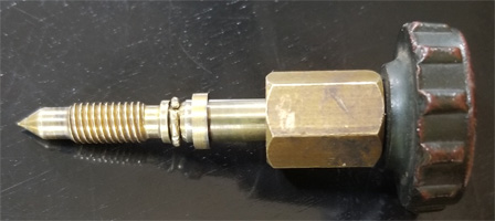 |
Figure 6 |
Insert the conical end of the valve stem into the valve body and turn it clockwise until it stops.
Slide the valve stem nut forward while turning it clockwise. Once you have the threads started, continue turning with your fingers until it becomes tight.
Gather your fuel & air tube, the metering rod and the spring. Slide the spring over the metering rod and then insert the rod into the fuel & air tube. Press down on the top of the metering rod down to ensure it can travel freely. Insert the fuel & air tube into the bottom of the valve. Turn it clockwise and snug with a 5/16” end wrench.
Place the valve body in your bench vise. Tighten the valve stem nut 1 turn and stop. Turn the valve stem to open it, then close it, and take note of how much resistance the stem offers you. If it is very easy to turn with little or no drag, your valve stem nut is not yet tight. Tighten the valve stem nut another full turn and try again. Continue this process until you feel a good bit of drag turning the wheel.
 Note: This is the safety check of the lantern’s retainer stop. It is critical that your lantern passes this test.
3.2 Test the valve stem retainer stop. Turn the valve wheel fully counterclockwise until it stops. Once you have reached this point, briefly try to turn it counterclockwise even farther. If it turns, your retainer stop has opened around the valve stem and needs to be repaired. This would most likely happen with a 242 series lantern that had valve stem disassembled but I recommend you do this test regardless of what lantern you are rebuilding.
If it is “locked” and will not turn any further, the retainer stop is working properly. Return the stem to the fully clockwise (closed) position.
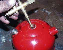
3.3 Install the valve. Insert the fuel & air tube into the center hole in your fount and turn the valve clockwise to install it (Figure 7). Turn until it snugs up, then continue turning it with just your hands as far as you can without assistance from a tool.
![]() Thread lock is not required when installing the valve. I have been rebuilding lanterns and stoves for 20 years and have never needed it. Coleman sometimes used Loctite Red #262 or Gasoila Hard-set. You can use these, or Loctite Red #545 if you choose to, but never use pipe-dope or Teflon tape.
Thread lock is not required when installing the valve. I have been rebuilding lanterns and stoves for 20 years and have never needed it. Coleman sometimes used Loctite Red #262 or Gasoila Hard-set. You can use these, or Loctite Red #545 if you choose to, but never use pipe-dope or Teflon tape.
Place the fount upside-down in your bench vise, just as you did when removing the valve. Use firm and even pressure as you slowly rotate the fount. Once you feel the valve starting to get tight, continue to turn it until the valve stem reaches the proper "clocking" position (Figure 8).
 |
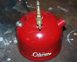 |
Figure 7 |
Figure 8 |
Please refer to the pictures you took of your lantern when determining the proper position of your valve. Lanterns in the 242 series manufactured before the mid-1940s were made with the pump to the left of the valve wheel and right of the fuel filler cap. Canadian 200 series lanterns were made the same way.
Most 242 series lanterns made after the mid-40s, and all US-built 200 series lanterns were made with the pump to the right of the valve wheel.
Take the fount out of the vise, set it down and look at the position of the valve stem. Confirm that it is centered between the pump and the filler cap.
Do not let the position of the decal fool you. Return your lantern to the vise if minor adjustments are necessary.
Oops? If you bend the fount a little don't worry. Using the vice and apply pressure to the fount in the opposite direction of the bend.
3.4 Install the check valve. If you left the check valve in your lantern earlier, you can bypass this step.
Figure 9 shows a new check valve, and that they come with an O-ring. If you are going to reuse your original check valve you may want to add an O-ring as it will seal the fount-to-valve connection much better. I went to Ace® Hardware and found a very close match. These O-rings are 1.5mm in width, I.D of 7mm and O.D. of 10mm and they are made of Viton.
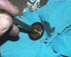
Take your new (or cleaned) check valve and remove the air stem. Tilt the fount on its side and drop the check valve down into the cylinder. Use a flathead screwdriver to turn it clockwise until snug.
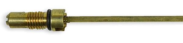 |
Figure 9 |
3.5 Install the air stem. Lower the bottom end of the air stem into the pump plunger hole, then turn it clockwise to install in the check valve. Finger-tight is fine.
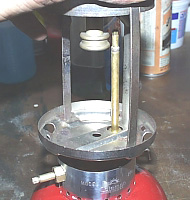
3.6 Install the pump. Gather your pump assembly to include the pump clip or screws. Ensure that all of the excess oil has been removed from in and on the pump (Figure 10).
Direct the bottom of the pump down into the cylinder, guiding the air stem into the hollow pump shaft (Figure 11). At the same time, start tucking the edges of the pump cup inside the cylinder. Ensure that the cup does not roll or catch an edge as you slide it down in the cylinder.
 |
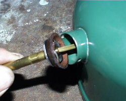 |
Figure 10 |
Figure 11 |
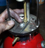
Press the pump down in the cylinder. Carefully fit the pump cap over the edge of the pump cylinder, ensuring that the “oil” hole is above the shaft and that the screw/clip holes in the pump cap are aligned with those in the fount (Figure 12). Press down evenly and firmly to align the holes.
With the pump cap properly aligned, install the pump clip or screws to secure it. If you have a pump clip, insert one end in one hole, then use needle nose pliers to guide the other end into the second hole (Figure 13). It can be a tight fit so use caution, so you don't scratch anything.
Press the pump all the way to the bottom and rotate it clockwise until it stops.
 |
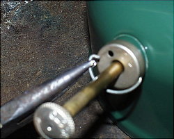 |
Figure 12 |
Figure 13 |
3.7 Install the fuel filler cap. Set your filler cap insert on the fount and then loosely install the filler cap over it. Before the cap gets tight, install the insert screw. Once you have it started, fully tighten down the filler cap and then take a screwdriver and tighten the insert screw. You will notice a space between the screw and the cap--this is normal.
3.8 Pressure test the fount. Fill the fount at least half-way with fuel, then install the filler cap and tighten it. Before starting, wipe off any fuel that may have spilled on the fount. Set it on a dry paper towel for testing. Keep your ears and eyes open for leaks.
![]() Note: These tests assume that your fuel filler cap/gasket is new, or in very good working condition.
Note: These tests assume that your fuel filler cap/gasket is new, or in very good working condition.
Place the valve wheel on the end of the valve stem and make sure the valve is fully clockwise. Rotate the pump handle one turn counterclockwise, grab the pump with your fingers and plug the hole with your thumb. Over-pressurize the lantern by giving it 50+ pumps then rotate clockwise to close the pump.
Listen for air escaping and watch for wet spots. Areas to look closely at:
Valve-to-fount junction. Watch for the slightest amount of dampness or bubbles from around the threads. If you note a leak you probably need to turn the valve in the fount one more turn.
Valve stem nut. Look and feel for dampness along the bottom of the valve stem and nut. A leak here indicates that the stem packing has not been sufficiently tightened.
Bottom of the fount. If you see ANY dampness on the bottom of the fount or on the paper towel, you need to find the source of the leak.
Warning: ANY hole or crack in the fount renders the lantern unsafe to use. Don't take the chance by trying to fix it with body putty or POR-15®. Get a replacement fount or set it on a shelf for display. DO NOT USE THE FOUNT.
3.9 Test the check valve. Turn the pump handle counterclockwise two full turns to open the check valve. Lightly rest your finger over the hole on the pump. Do not press down. What does the pump do?
If it does nothing, your check valve is working properly.
If it raises up, it is leaking. How fast it comes up tells you how bad the leak is. If it rises bottom to top in under 5 seconds, it is leaking too much to be safe.
Remove the pump and shoot some carburetor cleaner at the check valve to see if you can clean it better. If you cannot stop the leak, I recommend you remove the check valve.
If the pump rises slower than previously mentioned, you might be okay because the air stem is a positive stop (supplement) for the check valve.
You are the only one who can decide if your check valve is working well enough to be safe. The 5 second rule is only a guideline.
3.10 Install the frame rest. Rotate your lantern so that the valve stem is to your left and turn the tip cleaner stem horizontal. Be careful not to scratch the fount. Take the frame rest and insert the tip cleaner stem into the smaller hole, and from the inside. Push the rest as far left as you can. Now slightly squeeze it until the left side slips over the valve stem (Figure 14). Now move the rest back so that it sits normally on the fount.
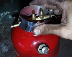 |
Figure 14 |
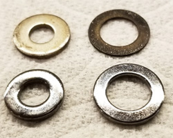
3.11. Install the frame washers. Before you install your generator is a good time to set both washers on your valve. The smaller washer (1/4) fits the center stud for the frame nut. The larger washer ( 3/8") will sit under the generator.
If a previous owner lost the washers, I recommend you go find replacements. The smaller washer for the center post is a 1/4" washer with an OD of 9/16". The larger washer is an odd shape: it has an OD of 3/8" and an OD of about 5/8". Go to the specialty section of a small hardware store (I did not find them at Home Depot® but did at Ace®) and look through their selection. Figure 15 shows originals (top) and replacements I found locally. Figure 16 shows both washers installed on a lantern.
The reason that second washer is an odd size is due to the 200A frame. Viewed from the bottom, there is a channel running front-to-back and the generator washer sits inside this channel. If you don't have the right sized washer it will not fit in this channel and your frame will not sit properly on the frame rest.
 |
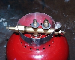 |
Figure 15 |
Figure 16 |
3.12 Install the generator. Unwrap your new generator using caution not to allow the internal parts to fall out. Slide the jamb nut over the generator and let it slide to near the bottom. Rotate the Tip Cleaner Stem on your lantern so that the lever is pointing up.
Pull the tip cleaner rod out of the bottom of the generator about an inch. While holding the generator in one hand, insert the crooked end of the rod into the hole in the eccentric block as shown in Figure 17. Once inserted, rotate the tip cleaner stem down to secure the rod. Slowly lower the generator tube down onto the valve and DO NOT force it. You may need to rotate it a little to get it all the way down.
Stand the generator straight up and use your fingers to snug the jamb nut. Do not tighten yet.
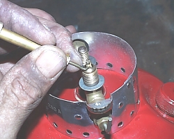 |
Figure 17 |
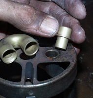
3.13(a) Reassemble the frame (200 Series). Get your frame, U-tube, venturi, ventilator bracket and burner tube with its burner cap & screen down in front of you. Grab the burner tube and note how the lock nut is positioned as it may have moved when you removed and cleaned the burner tube.
The position on the burner tube can be adjusted up or down, and it determines the overall length of the burner. To locate the best initial position, turn the lock nut clockwise to move it toward the burner cap until it runs out of threads. Now back it off two full turns.
Set the Frame upright on your workbench. Place the small end of the venturi in the hole that is off-center on the frame (Figure 18). Then take the ventilator bracket and place it directly over the center hole in the frame top. Rotate the bracket so that the concave side faces toward the back of the frame.
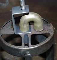
Look at your U-tube to determine which end has threads. Place the end without threads down on the Venturi. Rotate the other end so that it sits directly over the frame's center hole (Figure 19).
Hold the U-tube with one hand and the burner tube in the other. Insert the burner tube into the center hole of the frame from the bottom (Figure 20). Push the tube upward while rotating it clockwise. It will pass through the frame and ventilator bracket to thread into the U-tube. Turn it until the lock nut reaches the frame, then use a 5/8” end wrench to tighten the lock nut.
 |
 |
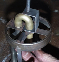 |
Figure 18 |
Figure 19 |
Figure 20 |
3.14(b) Reassemble the Frame (242 Series). Set your frame, ventilator rod, burner tube and burner cap & screen down in front of you. Thread the ventilator rod into the top of the frame and tighten with a 7/16” wrench. If the burner cap & screen was separated from the burner tube, thread them back together and hand-tighten.
Insert the burner tube into the center hole in the frame, from the bottom. Tighten the burner cap & screen by hand.
3.15 Install the Frame. Gently lower the bottom of your frame over the top of the generator. As you lower it, guide the top of the generator towards the angled hole in the air intake tube (200 series) or burner (242 series) while aligning the center hole in the frame bottom over the valve stud.
Lower the frame down on the frame rest. Aligned properly, it will sit level on the rest, and the generator will be vertical with the tip disappearing into the burner (Figure 21).
Install the frame nut on the center stud and snug it down by hand (Figure 22). Turn the lantern so that it is facing you and center the valve stem nut inside the hole in the frame rest (Figure 23). Keep the frame rest from moving and slowly tighten the nut with a 7/16” wrench until it is tight. Try twisting the frame side-to-side. If it is sufficiently tight you will not be able to move it without excessive force.
Once you have the Frame tightened, apply your 7/16” wrench to the generator jamb Nut and tighten it.
 |
 |
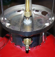 |
Figure 21 |
Figure 22 |
Figure 23 |
3.16 Install the valve wheel (200 series only). Place the valve wheel over the end of the valve stem and ensure the stem is turned fully clockwise. Set the direction disc inside the recessed area of the wheel and then thread the screw into the end of the stem. Rotate the direction disc until the arrow is pointing up, then hold it there while tightening the screw.
Caution: Ensure you have a fire extinguisher close-by before proceeding!
3.17 Prepare for lighting. Take a new mantle and install it on your lantern. Make sure you snip the ends of the string off. Light it on fire and allow to burn completely.
Twist the pump handle counterclockwise and pump your lantern 30 times. Turn the pump handle clockwise to close. Observe the lantern for a few minutes before going any farther. Watch and listen for any indications of a leak as you did earlier.
Rotate the tip cleaner stem a few turns and leave the lever pointing down. Turn the valve wheel counter-clockwise one or two full turns and listen. You should hear the hissing of a small stream of air being released inside the burner. Within a few seconds the hissing should change to a “spitting” noise. Once you hear the spitting noise, turn the valve wheel off.
3.18 Light the lantern. Place a lit match or a lighter under the mantle. Turn the valve wheel about 1/4 turn counterclockwise to open the valve. The mantle will flame-up and dim and cough for a few moments, but then should start to burn steady, but perhaps dim.
Once the lantern is burning steady, slowly open the valve all the way. Give it additional pumps to fully pressurize it and increase the brightness. It should burn steady with little or no flickering or pulsing. Continue to watch for dampness on and around the lantern.
Congratulations! The final few parts of your lantern can now be installed. When you install the ventilator, don’t tighten the ball nut. Always leave it just a little loose so that it doesn’t chip the porcelain enamel.
 |
 |